Voltage to Current Converter Circuit:
Occasionally in industrial electronics, it is necessary to provide a current proportional to certain voltage, even though the load impedance may vary. A circuit which can perform this job, is called a Voltage to Current Converter Circuit. The circuit of Voltage to Current Converter Circuit is shown in Fig. 36.25.
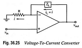
The circuit is similar to that of positive scaler shown in Fig. 34.1 except that the feedback resistor Rf is replaced by a load impedance ZL. For a single input, the current in the load impedance ZL is given by
![]()
From above Eq. (36.10) it is obvious that the output current iL is independent of load impedance Zf and is proportional to the input voltage vin. This is because of the virtual ground at the inverting input terminal of the op-amp. Such a circuit is employed in analog-to-digital converter (ADC).
One good thing about the op-amp voltage-to-current converter is that it can be driven by a voltage source which is itself not capable of supplying the load current called for by Eq. (36.10). This is because the voltage source only has to drive a noninverting op-amp, whose input impedance is very high (many megohms). The load current itself is supplied by the op-amp.
Another version of the voltage-to-current converter is given in Fig. 36.26. In this circuit, the load is grounded, and an input voltage controls the load current.
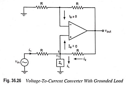
Let v1 be the voltage at noninverting input terminal (Fig. 36.26).
Applying Kirchhoff’s current law at node 1, we have
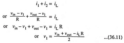
Since the op-amp is in the noninverting mode,
![]()
Then output voltage,
![]()
Substituting v1 = vout/2 in Eq. (36.11), we have
![]()
or load current,
![]()
The above Eq. (36.12) shows that the load current depends upon the input voltage vin and resistor R. It is an ideal circuit for low-voltage dc and ac voltmeters, LED and zener diode tester.