Voltmeters and Multimeters Articles:
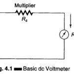
DC Meter: The most commonly used dc meter is based on the fundamental principle of the motor. The motor action is produced by the flow of a small amount of current through a moving coil which is positioned in a permanent … (Read More)
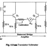
Transistor Voltmeter (TVM): Direct coupled amplifiers are economical and hence used widely in general purpose low priced VTVM’ s. Figure 4.9 gives a simplified schematic diagram of a dc coupled amplifier with an indicating meter. The dc input … (Read More)
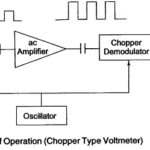
Chopper type DC Amplifier Voltmeter (Microvoltmeter): Chopper type DC Amplifier Voltmeter the dc input voltage is converted into an ac voltage, amplified by an ac amplifier and then converted back into a dc voltage proportional to the original input signal. The balanced … (Read More)
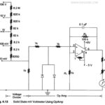
Solid State Voltmeter: Figure 4.13 shows the circuit of an electronic voltmeter using an IC OpAmp 741C. This is a directly coupled very high gain amplifier. The gain of the OpAmp can be adjusted to any suitable … (Read More)
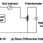
Differential Voltmeter: The Differential Voltmeter technique, is one of the most common and accurate methods of measuring unknown voltages. In this technique, the voltmeter is used to indicate the difference between known and unknown voltages, i.e., an unknown voltage is compared … (Read More)
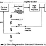
DC Standard Differential Voltmeter: A basic DC Standard Differential Voltmeter can be operated in different modes. The three basic modes of operation are as a dc voltage standard, as a dc differential voltmeter, and as a dc voltmeter (conventional). 1. DC Voltage Standard: A + 1 … (Read More)
AC Voltmeter using Rectifiers: Rectifier type instruments generally use a PMMC movement along with a rectifier arrangement. Silicon diodes are preferred because of their low reverse current and high forward current ratings. Figure 4.16 (a) gives … (Read More)
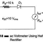
AC Voltmeter using Half wave Rectifier | AC Voltmeter using Full wave Rectifier | Multirange AC Voltmeter: AC Voltmeter using Half wave Rectifier – If a diode D1 is added to the dc voltmeter, as shown in Fig. 4.18, we have … (Read More)
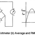
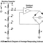
Average Responding Voltmeter and Peak Responding Voltmeter: A simplified version of a circuit used in a typical average responding voltmeter is given in Fig. 4.23. The applied waveform is amplified in a high gain stabilized amplifier to a reasonably high level and … (Read More)
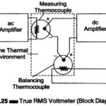
True RMS Voltmeter: Complex waveform are most accurately measured with an rms voltmeter. This instrument produces a meter indication by sensing waveform heating power, which is proportional to the square of the rms value of the voltage. … (Read More)
Considerations in Choosing an Analog Voltmeter: Considerations in Choosing an Analog Voltmeter has the following factors are to be considered. 1. Input Impedance The input impedance or resistance of the voltmeter should be as high as possible. It should always be higher than … (Read More)
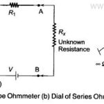
Series Type Ohmmeter: A D’ Arsonval movement is connected in series with a resistance R1 and a battery which is connected to a pair of terminals A and B, across which the unknown resistance is connected. This … (Read More)
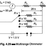
Multirange Ohmmeter: The Multirange Ohmmeter circuit shown in Fig. 4.28 (a) is only for a single range of resistance measurement. To measure resistance over a wide range of values, we need to extend the ohmmeter ranges. This type of ohmmeter is … (Read More)
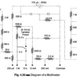
Working Principle of Multimeter: A multimeter is basically a PMMC meter. To measure dc current the meter acts as an ammeter with a low series resistance. Range changing is accomplished by shunts in such a way that the current passing through … (Read More)
