What is a Cooling Tower? – Types of Cooling Tower
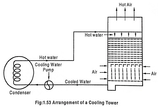
Cooling Tower is used to cool the water, and its height is about 140 Meters. The hot water is to pumped the tower top and falls down through the tower and is broken into small particles while passing over the baffling devices. Air enters the tower from the bottom and flows upwards. The air vaporizes a small percentage of water thereby cooling water falls down into tank below the tower from where it is pumped to the condenser and cycle is repeated.
Type of Cooling Tower:
(a) According to the construction material
- Timber – for small tower
- Ferro – concrete – for large capacity stations requiring – high initial cost
- Multi deck concrete towers – for large steam stations
- Metallic
(b) According to the nature of air draught
- Atmospheric (or) natural draught cooling system
- Mechanical draught cooling tower
(c) Air – cooled (or) dry – type cooling tower
Atmospheric (or) natural draft cooling towers
In this, the natural air provides the required cooling without the use of fans. This is further classified into three types.
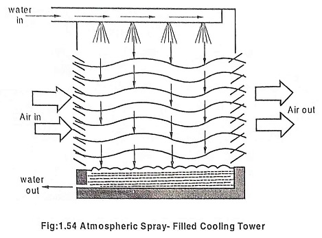
1. Natural Draft spray filled towers
In this, the air enters through the lower sides and flows in the transverse direction across the unit. The amount of air flow depends on the wind velocity. Its capacity varies from 50 – 100 liters per min per m2 of base area. This is not suitable for high capacity thermal plants. The arrangement is shown in the Fig.1.54.
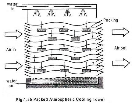
2. Natural draft packed type tower
It is similar to that of the above type except that water distributing troughs are used. This helps to have better surface exposure of water by breaking it into small droplets. This is rarely used for thermal power plants as the capital cost and pumping head required are high. This arrangement is shown in Fig.1.55.
3. Hyperbolic Cooling Tower
This tower is made of steel reinforced concrete structure mostly stack. The shape of the stack is hyperbolic in profile and circular in cross section. The operation is similar to that of Natural draft spray cooling tower.
The air flow is established by chimney action ie due to density difference between atmospheric air and air inside the tower. Because of more water vapour and higher RH value which is lighter than air, the net humidity of the air becomes lower than the surrounding air. This difference in density provides necessary draught. Since the difference in density is very small, the height required is considerably large.
Mechanical Draft Cooling Towers
Mechanical draft towers are mostly preferred than the natural draft towers because 1. They provide closer approach to WBT, 2. They have reduced spray and wind losses, 3. They have higher efficiency and 4. They require less ground area.
Instead of depending on the natural draught and wind velocity, it employees fans to move air through the tower. By this, the efficiency of the system is increased and required amount of air velocity can be readily obtained.
Mechanical draft is classified into three types.
1. Forced draft tower, 2. Induced draft counter flow tower 3. Induced draft cross – flow tower.
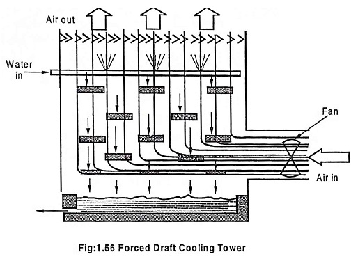
1. Forced Draft Tower
In this, a fan is located at the bottom of the tower and the air is forced from bottom to the top. This arrangement is shown in Fig.1.56.
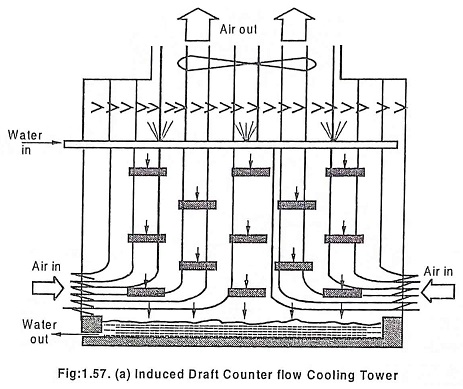
2. Induced Draft counter – flow tower
In this type, the fan is located on top of the tower. This arrangement is shown in Fig.1.57(a). The air enters louvers located on sides of the tower.
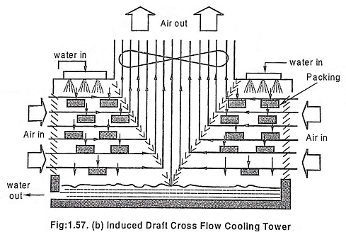
3. Induced draft cross-flow Tower
In this, the flow of air is in horizontal direction and the flow of water is in vertical direction. The fan is centered at the top. The drift eliminators turn air towards outlet fan. Lower air static pressure and less resistance to flow of air are the features of this system.
Air Cooled or Dry-type Cooling System
Since the thermal pollution and water requirement are major problems with the wet type cooling towers, it can be replaced by dry type cooling system. In dry type, the heat is directly rejected to the atmosphere.
The dry type cooling tower is classified into two types as
- Indirect type 2. Direct type
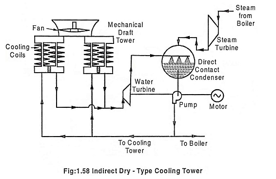
1. Indirect dry type or HELLER COOLING system
The arrangement is shown in the Fig.1.58. The collected condensate is partially fed to the cooling coil and partially fed to the boiler. The cooling coil is cooled by the air. The cold water coming out of the cooling water is sent to the condenser through the nozzle and water turbine. The water turbine is used to utilize the pressure and elevation head between the cooling coil and condenser. There is no evaporation loss in the system as there is no direct contact.
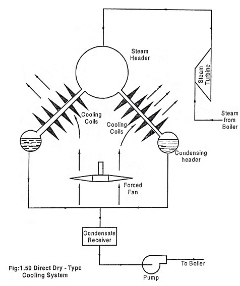
2. Direct Dry type cooling system
The arrangement of direct dry type cooling system is shown in Fig.1.59. Through the air cooled coil, the turbine exhaust is made to flow. A forced fan is used to pass the air through the coil. In the condensate header, the condensate is collected and passed to the boiler through feed pump.
The major difference between direct and indirect type of cooling system is that the direct system handles large amount of steam than lesser amount of steam in the indirect system.
